Customizable peripheral nuclear fuel Assembly for attaining significant reduction of radiation-induced embrittlement to reactor pressure vessels and associated welds
Background
Industry studies indicate that the reactor pressure vessel may be a limiting component with respect to attaining the desired life and life extension, i.e., Long Term Operation (LTO) / Subsequent (Second) License Renewal (SLR), for many nuclear power plants. The primary reactor vessel life attainment issue is concerned with the prevention of non-ductile failure of the reactor vessel welds, which is subject to neutron radiation-induced embrittlement effects. For those vessels where this concern exists during their anticipated operational life, the implementation of neutron flux reduction programs can play a significant role in attaining desired reactor lifetimes. Because fluence impacts to the reactor vessel welds build up over time, effective fluence reduction requires implementing a program as early as possible to minimize the amount of incremental fluence reduction needed in each future cycle after program implementation (see graph below).
One available hardware product to achieve moderate fluence reduction is the Westinghouse unclad Peripheral Power Suppression Assembly (PPSA) [NF-FE-0050]. However, if more significant levels of fluence reduction to the vessel is required, the Westinghouse Shielding Fuel Assemblies (SFAs) can be deployed on the periphery of the core. SFAs can be utilized in concert with the PPSAs to maximize the attainable fluence reduction.
The SFA design is the direct result of applying Westinghouse knowledge of the reactor system and functional relationships between SFAs and the system as a whole, providing an integrated solution that achieves target flux reduction goals in concert with low leakage fuel management, PPSAs and other fluence reduction strategies.
Description
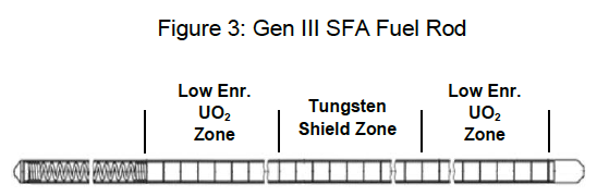
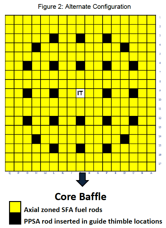
The SFA design is customizable to the particular needs of the individual plant and is typically composed of: (1) a series of rows of stainless steel rods that displace the fuel rods in the lattice of peripheral fuel assemblies near the baffle, and (2) axial zoned fuel rods for the remaining fuel rod lattice locations where part of the central axial extent is composed of parasitic absorber material (such as stainless steel, tungsten or hafnium hydroxide) while the end zone regions of the rods utilize low enriched UO2 pellets (see Figures 1 and 3). The SFA fuel rod design can be customized to have an increased diameter to increase the shielding efficiency. This leads to additional changes to the overall fuel assembly skeleton design.
PPSAs can be inserted in the guide thimble locations of the SFAs to increase the overall fluence reduction that can be attained.
The typical arrangement SFAs, when deployed in-reactor, will affect the power peaking and the linear heat margin of each operating cycle. Thus, one must investigate and understand these fuel cycle impacts when customizing the SFA design for the particular situation.
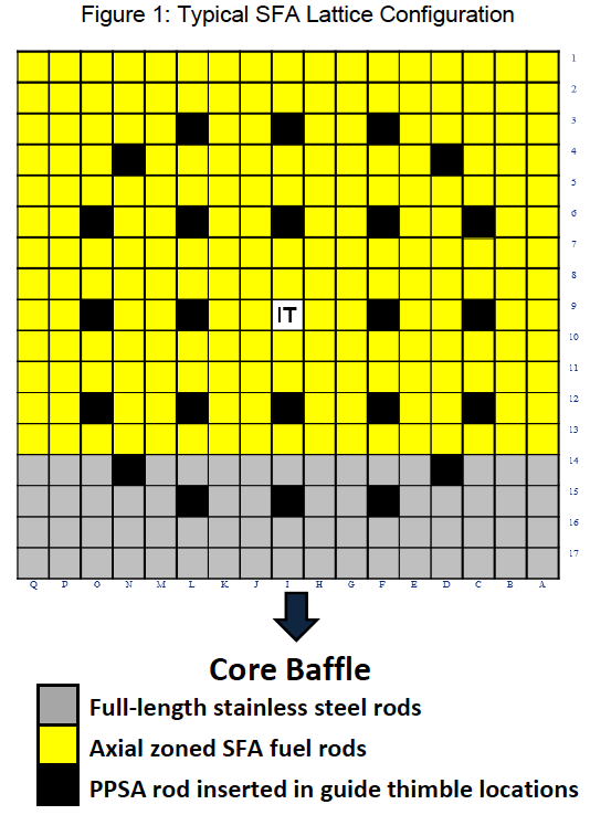
There are alternate SFA lattice arrangements that do not utilize fuel length stainless steel rods but instead use the axial zoned SFA fuel rods throughout the assembly (see Figure 2),
Figure 2: Alternate Configuration
These designs offer less fluence reduction than the typical arrangement but have the advantage of reducing the impacts on core power peaking and the erosion of linear heat rate margin.
Figure 3: Gen III SFA Fuel Rod
Benefits
- SFAs are designed to support significant (e.g, factor of 10) fluence reduction goals for Reactor Pressure Vessel materials and associated critical reactor vessel welds as customers address the U.S. NRC amended rule on Pressurized Thermal Shock or similar requirements in other countries or when addressing discovered RPV issues like hydrogen flaking.
- A customizable design to address the particular plant’s fluence reduction needs.
- Designed to work singularly or in concert with low leakage fuel management strategies.
- Supports Long-Term Operation (LTO) / Subsequent (second) License Renewal (SLR) goals.
Current Interest
There is currently renewed interest in deployment of Generation III SFAs in support of customers’ Long Term Operation (LTO) / Subsequent (Second) License Renewal (SLR) goals. We have performed studies for the planned deployment of SFAs for a few European customers for the purpose of significant fluence reduction to their nuclear reactor pressure vessels welds and materials.