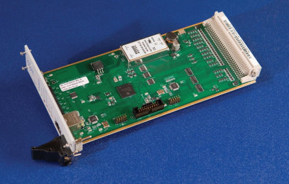
Figure 1-1 –ARCH Microcontroller Card
Current Regulating Controller Card (CRC)
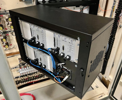
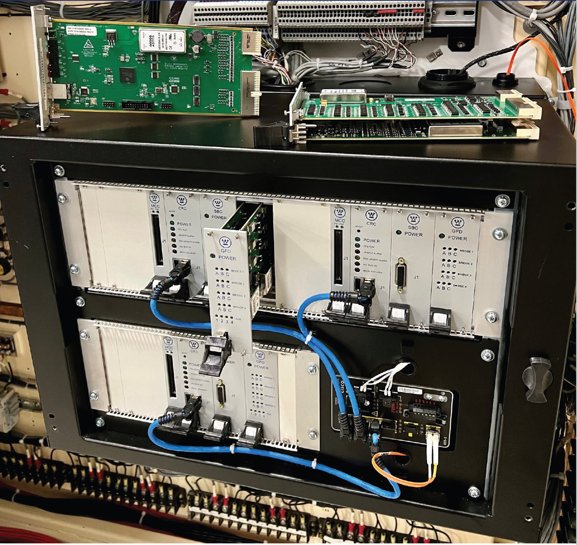
Figure 1-2 –ARCH control assembly is designed for ease of maintenance and installation, with the rear of the electronics assembly accessible.
The Westinghouse Solid State Rod Control System (SSRCS) has been in operation at many plants for over 30 years. This system has been very reliable but obsolescence concerns are increasing and personnel experience for the analog control system is difficult to maintain in the modern, digital world. The system also has limited diagnostics and can be time consuming to troubleshoot, increasing downtime.
For new plant applications, Westinghouse has deployed the Digital Rod Control System (DRCS) to twenty new plants to date, which are in various stages of startup. While possible to replace the Westinghouse SSRCS with a complete DRCS, this is a challenging single outage installation, and may be a higher risk proposition relative to typical outage schedule.
To this end, Westinghouse has developed a drop in replacement for the existing SSRCS power cabinet analog control card chassis that leverages the features and functions of the DRCS, while maintaining the cabinets, system architecture and power electronics. This new hybrid of a digital control system and existing power electronics provides a simplified path forward from analog to digital control. This system is the Westinghouse Advanced Rod Control Hybrid (ARCH).
ARCH is Westinghouse’s third generation digital rod control system, which incorporates over twenty years of digital rod control experience; starting with the Microprocessor Rod Control System (MRCS) installed in Sizewell B to the new generation of AP1000 and APR1400 DRCS Installations.
At its base installation, the system consists of an electronics control assembly that takes the place of the existing analog control cards, a redundant phase transformer network update and all new independent Movable Gripper circuitry and components for True Double Hold. This new system reduces the total card count from 20 total cards (7 types) per power cabinet to 12 total active control cards (4 types) and one built in backplane extender card. Also the existing -24VDC power supplies are no longer required and removed from the system, and the auctioneering diode assembly is replaced.
The new cards are industrial grade, IEEE based, IPC-A-610 Class 2 printed circuit cards, with modern components based around an industry standard, industrial safety grade, ARM Real-Time microcontroller. Microcontroller has a secure USB port for simplified firmware updates, to allow for future functionality and improvements.
The electronic assembly is pre-built and pre-wired for ease of installation into the cabinet. The card cage is hinged for ease of access to the rear component, and all interfaces are now connectorized, or landed on accessible modern compression style terminal blocks. Backplane connectors are IEC 61076 standard connector system.
Because the system is microcontroller based, coil timing is moved from the logic cabinet into the power cabinet, removing the need for current order surveillance. A simplified, single fault tolerant, control scheme is used that works in conjunction with the OvationTM Logic Cabinet Rod Control Upgrade. This will re-use existing cabinet wiring so installation will not require additional hardwired signals to be run from the logic cabinet to the power cabinets. All that is required is a single fiber-optic connection to each new electronic control assembly.
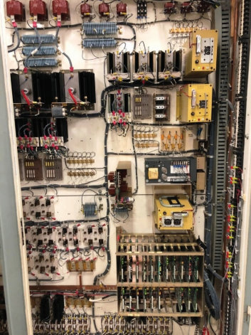
Figure 1-3 - Existing SSRCS Control Cards (Right Bay)
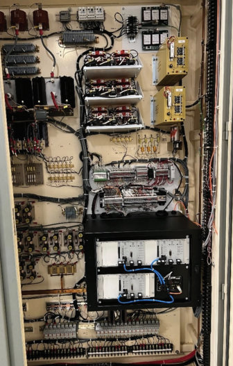
Figure 1-4 – New ARCH Control Cards
(Right Bay - Prototype)
Each set of cards is capable of controlling up to four SCR bridges. As such, with ARCH, the single Movable Gripper SCR Bridge and support circuity will be replaced with three individual bridges and support circuits, which will allow for true double hold. This removes the chance of a single fault on the stationary gripper causing a rod drop or slip. This also removes the need for the DC hold cabinet, as holding can be maintained on the Movable Gripper while the Stationary Gripper is de-energized for maintenance.
In addition, the existing single set of phase transformers is replaced with two redundant simplified phase transformers. This removes another single fault and allows the movable gripper to retain phase crossing and subsequently holding in the event of complete or partial failure of stationary gripper power.
With the capability of a localized microcontroller, cabinet parameters are continuously monitored and displayed on an Ovation workstation. This includes, but not limited to:
Advanced maintenance modes are also available for troubleshooting and testing, including the ability to exercise all signals and system logic/software without M-G set power and loads.
Existing main control room controls and indications can be retained, or replaced with soft controls. Ovation displays can be tailored to the customer’s needs, integration with other upgrades and plant specific HFE programs.
Ethernet communication enables setpoint modifications to be accomplished via soft display.
Single rod motion is coordinated via soft display, and existing control room lift disconnect switches can be removed or abandoned in place.
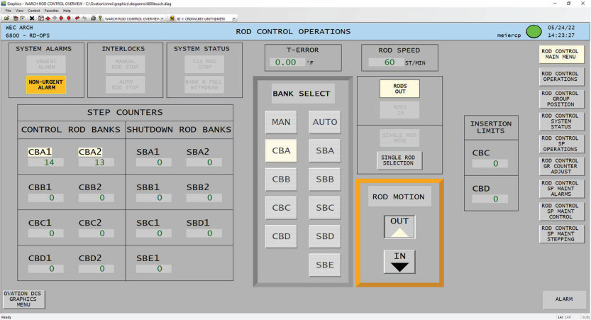
Figure 1-5 –Rod Control Main Display (Soft Control Implementation)
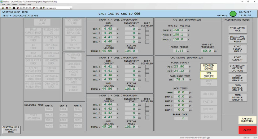
Figure 1-6 –Stationary Gripper CRC Status Display
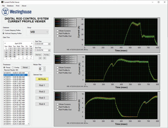
Figure 1-7 – Current Profile Viewer
ARCH captures current profiles for every step the system takes, and transmits then to a workstation for database archival. Database information can then be accessed via the Westinghouse Current Profile Viewer tool.
Troubleshooting is simplified by viewing the actual trace that caused an alarm. The trace is retrieved by group, date and time, and eliminates the need to attempt to recreate the condition, with a recorder attached, which may be difficult for intermittent error conditions.
Profile data can be archived for future predictive analysis of CRDM operation.
Beyond the base system installation, additional power cabinet components such as lift coil fuses and resistors and/or field terminal blocks can be upgraded as needed/desired with the modern equivalents used in the DRCS. Additional reliability updates can be implemented such as redundant power supplies for lift disconnect gating. This flexible approach will allow long-term system upkeep, consistent with the utilities operational, maintenance and financial strategies.


