Background
Through its acquisition of ABB Combustion Engineering Nuclear Power in 2000 and its current KWN joint venture in Korea, Westinghouse supports the supply of 14x14 and 16x16 Control Element Assemblies (CEAs) for Combustion Engineering Nuclear Steam Supply System (CE-NSSS) plants, including those based on System 80 design technology. Westinghouse supplies all of the various full strength and part strength CEA design types used by the current operating fleet of CE-NSSS reactors.
The benefits of using Westinghouse CEA designs include:
- Long design life, especially for designs using Silver – Indium – Cadmium (Ag-In-Cd) in the lower absorber section.
- Compatibility with CE-NSSS fuel and reactor internals.
- Ability to supply the complete portfolio of CE-NSSS CEA designs used in current operating reactors.
More than 35 years of successful operating experience with our CEA designs.
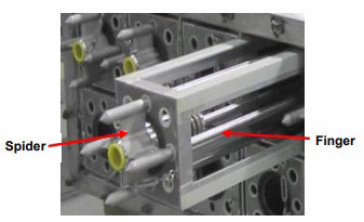
16x16 Five Finger CEA in a shipping container cradle
Description
A CEA consists of a cluster of control rods (fingers) attached to a central spider assembly. CEA fingers consist of one or more specified lengths of neutron absorbing material (typically B4C pellets and Ag-In-Cd slugs) enclosed in a hermetically sealed cladding tube. The spider assembly has a specially machined hub to engage the extension shaft of the Control Element Drive Mechanism (CEDM). The spider assembly also contains a spring mechanism within a central housing that assists with reducing CEA impact forces during a scram.
In CE-NSSS reactors, the CEA fingers function within the guide tubes of the fuel assemblies that reside in designated locations of the particular reactor core. In a CE-NSSS fuel assembly lattice, the guide tubes are located within 2x2 areas of the fuel lattice, and the CEA fingers are sized to fit within the inner diameter of the guide tubes.
The neutron-absorbing sections of the CEA are positioned axially to control the reactivity of the active length of the fuel rods during their periods of full and partial insertion into the core.
For the non-System 80 reactor types, CEAs are fully assembled at the factory prior to shipment and loaded into fuel assemblies at the plant site. Full strength CEAs typically consist of five fingers: four positioned in the four outer guide tubes and one positioned in the central guide tube of the fuel assembly. Some reactors use a four-finger design, also referred to as a “mini-dual,” that straddles two fuel assemblies. Additionally, there are part strength CEAs composed of a combination of full-strength fingers and fingers that contain lengths of weaker absorbers, such as Al2O3 and either stainless steel or Inconel. In some CE-NSSS reactors, two CEAs are coupled together so that their movements can be controlled by a single CEDM.
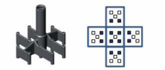
12 Finger CEA Spider and associated finger insertion pattern in fuel assemblies
In reactors based on System 80 design technology, the CEA spider, finger, and crimp nut parts are shipped to the plant site where the CEAs are assembled into the reactor Upper Guide Structure (UGS). The central guide tubes of the fuel assemblies are reserved for incore instrumentation; therefore, the CEAs for these reactors cannot contain central fingers. Two types of full strength CEAs are used in these reactors: 16x16 four -finger CEAs and 16x16 12- finger CEAs. The four-finger CEAs, which are placed in individual fuel assemblies, are used for power shaping functions and make up the first control bank to be inserted at high power. The 12- finger CEAs are used in the balance of control and shutdown banks, and each CEA has fingers that move within five adjacent fuel assemblies; a central fuel assembly that contains four CEA fingers and its four face-adjacent fuel assembly neighbors that contain two CEA fingers each.
The absorber materials used in full strength System 80 CEA designs include an upper section of B4C pellets and a lower section of either reduced diameter B4C pellets surrounded by felt metal or Ag-In-Cd slugs. The use of Ag-In-Cd improves the design lifetime of the CEA.
There are also four finger 16x16 part strength CEAs for System 80 design plants that use fingers containing Inconel (Alloy 625) slugs.
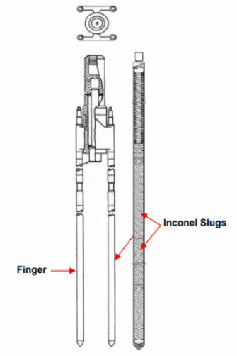
System 80 Part-Strength CEA
Experience
The operating experience of our CEAs has been exemplary. Our CEAs have benefitted from design modifications based on field operating performance data. The design evolutions of the various CEA types have improved margins to Irradiation Assisted Stress Corrosion Cracking (IASCC) of the cladding and have improved wear performance of both the fingers and the fuel assembly guide tubes, leading to excellent performance.
We have never encountered incomplete rod insertion (IRI) in any CE-NSSS reactor with our CEA designs.
The lifetime of the CEAs in non-System 80 reactors has been extended by increasing the lengths of the lower Ag-In-Cd absorber sections and actively managing the shuffling of CEAs among the high cumulative neutron flux (high duty) locations. These shuffles are possible because the ungrappled CEAs remain in fuel assemblies during a refueling outage. CEA lifetimes have been increased for System 80 plants by replacing the lower B4C absorber / felt metal section with Ag-In-Cd slugs. Plants based on System 80 technology do not shuffle CEAs between core locations since they reside in fixed locations of the UGS during a refueling outage.